
Product Categories
News
Contact Us
Tel: +86-0371-65621392Fax: +86-0371-86616825
E-mail: info@haomei.biz
Address:No.14 Waihuan Road, New district, Zhengzhou, China
ZIP: 450046

Concrete Batching Plant Schematic Diagram
Writer:Admin Time:26/08/06A concrete batching plant diagram is a core technical reference document for equipment selection, plant planning, installation, construction, operation, and maintenance. It is not merely a visual representation, but a structured technical diagram strictly drawn according to functional zoning, material flow, and equipment parameters. A standard batching plant schematic diagram typically includes two types: an elevation system diagram and a plan layout diagram. The former presents the vertical hierarchy of equipment, while the latter plans the plant's flow and boundaries. A complete diagram can be clearly broken down into five major functional modules, each with its own location, parameters, and connection logic following unified industry technical specifications.
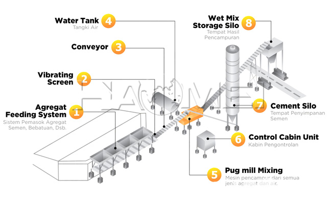
The aggregate batching and feeding unit is the front-end feeding module in the schematic diagram, usually located on the side of the site or in the front feeding area. In a standard commercial concrete plant schematic diagram, this unit is centered around a multi-compartment aggregate batching machine. The mainstream HZS180 concrete batching plant is equipped with four independent batching compartments, each with a volume of 15-20 m³, capable of simultaneously storing four different particle sizes of sand and gravel aggregates; it is equipped with an independent electronic weighing and metering device, with aggregate metering errors strictly controlled within ±2%. A closed belt conveyor connects to the batching machine, with a standard conveying angle of 18°-23°. This ensures efficient aggregate conveying while preventing material spillage and dust dispersion. The schematic diagram clearly indicates the total belt length and vertical lifting height for precise matching of site elevation differences and civil engineering foundation construction.
The mixing core unit is located at the vertical center of the schematic diagram and serves as the core reference benchmark. Most mainstream commercial concrete mixing plants are equipped with a twin-shaft mixer, specifically the JS3000 model for the HZS180, with a nominal batch discharge capacity of 3000L and a rated mixing power of 2×55kW. The schematic diagram clearly indicates the location and opening size of the mixer's inlet and outlet. The top of the mixer is equipped with a pulse-jet bag filter with a processing air volume of no less than 2000m³/h, effectively suppressing dust overflow during the feeding stage. Below the main unit is the finished product unloading area, with a standard unloading height set at 3.8-4.2m, accommodating the receiving height of mainstream 10-15 cubic meter concrete mixer trucks. The diagram will also indicate vehicle parking positions and passage widths.
The powder storage and conveying unit is shown in the diagram as vertical cylindrical tanks, symmetrically arranged on both sides of the main unit. Commercial standard stations typically have 3-4 powder silos, each with a nominal volume of 1000t, used for storing cement, fly ash, mineral powder, and other cementing materials. The top of the silo is equipped with a pressure safety valve, a continuous level gauge, and a dust removal device. The bottom connects to the main unit's metering hopper via a tubular screw conveyor, with a screw conveying efficiency of 60-80t/h and a powder metering error ≤±1%. The diagram will clearly indicate the total tank height, leg span, and foundation embedded part locations, directly guiding the construction and pouring of the site's civil engineering foundation.
Auxiliary units are distributed in the functional corners of the schematic diagram, including the central control room, water and admixture supply systems, and environmental protection facilities. The central control room is typically located in a well-lit area on the side of the site, facilitating full-process monitoring of production status by operators. The water and admixture systems are independently located next to the main unit, both using high-precision electronic scales with a measurement error of ≤±1%. The schematic diagram also indicates the specific locations and dimensions of the enclosed raw material shed, three-stage sedimentation tank, and vehicle washing platform, fully complying with green production requirements.
From an engineering application perspective, the core value of the concrete batching plant schematic diagram lies in its precise guidance for site planning. Taking the HZS180 concrete batching plant as an example, the schematic diagram can calculate that the complete plant area, including raw material storage, production area, and auxiliary office area, is approximately 15-20 acres. It also optimizes the flow of vehicles entering the site and leaving the finished product area, avoiding congestion. For equipment installation and daily operation and maintenance, the schematic diagram is also a core reference for equipment positioning, pipeline layout, and fault location diagnosis, making it an indispensable technical foundation document for the entire lifecycle management of the concrete batching plant.